Design Guide for Security Surveillance Systems in Underground and Enclosed Spaces
A comprehensive engineering reference for deploying reliable, maintainable, and compliant security surveillance systems in underground parking garages, metro passages, utility tunnels, plant rooms, and enclosed storage zones — addressing low-light, humidity, EMI, emergency linkage, and O&M constraints.
System Overview
This guide defines an Underground/Enclosed-Space Security Surveillance System for environments such as underground parking, metro passages, utility tunnels, underground plant rooms, and enclosed storage areas. The system delivers usable imaging, controlled access, corridor-type perimeter and line-crossing protection, and emergency alarm with linked response, while explicitly addressing underground constraints: insufficient lighting, humidity and water ingress, dust and exhaust, echo and noise, EMI, escape and emergency linkage, and maintenance reachability.
The scope includes video capture and recording, event analytics, intercom and distress alarms, access control for entrances and restricted rooms, corridor intrusion and line-crossing protection, central monitoring, incident playback and evidence export, and integrations with UPS, power distribution, fire systems, and door hardware. The system is designed around the core value of "Safety & emergency first + image usability + link reliability + sustainable O&M," producing a system that remains actionable when the underground environment degrades.
Typical delivery results include a complete design package (drawings, BOM, calculations), installed cameras, doors, and sensors, network cabinets, VMS and ACS servers, tested link redundancy, acceptance reports, O&M manuals, and spare parts. All design decisions are grounded in site-survey data — lux measurements, RH readings, EMI zone mapping, and authority approvals — rather than generic assumptions.
Key Design Philosophy: "Safety & emergency first + image usability + link reliability + sustainable O&M" — every design decision must remain actionable when the underground environment degrades.
Scope & Applicability
The following table summarizes what is in scope, out of scope, and the primary system inputs and outputs for this design guide.
| Category | Details |
|---|---|
| In Scope | Video capture & recording, event analytics, intercom & distress alarms, access control, corridor intrusion protection, central monitoring, incident playback, fire/UPS/door integrations |
| Out of Scope | City-wide public safety cloud platforms, facial recognition at scale without legal basis, high-security military-grade crypto solutions |
| Inputs | Camera streams, door/controller events, intrusion sensors, duress buttons, environmental alarms (water/smoke/temp), UPS/power alarms, operator commands |
| Outputs | Live views, recordings, alarms, PTZ commands, door unlock/lock commands, PA/intercom triggers, emergency linkage outputs, reports/audit logs |
| Key Dependencies | Structured cabling, PoE switching, fiber backbone, UPS, grounding, fire system interface, equipment cabinets, maintenance access paths |
System Architecture
The overall system architecture follows a left-to-right layered model, from field sensing devices through edge networking infrastructure to the central platform and external support systems. Each layer has clearly defined responsibilities, and redundant paths are built in at every critical junction to ensure continuous operation even under partial failure conditions.
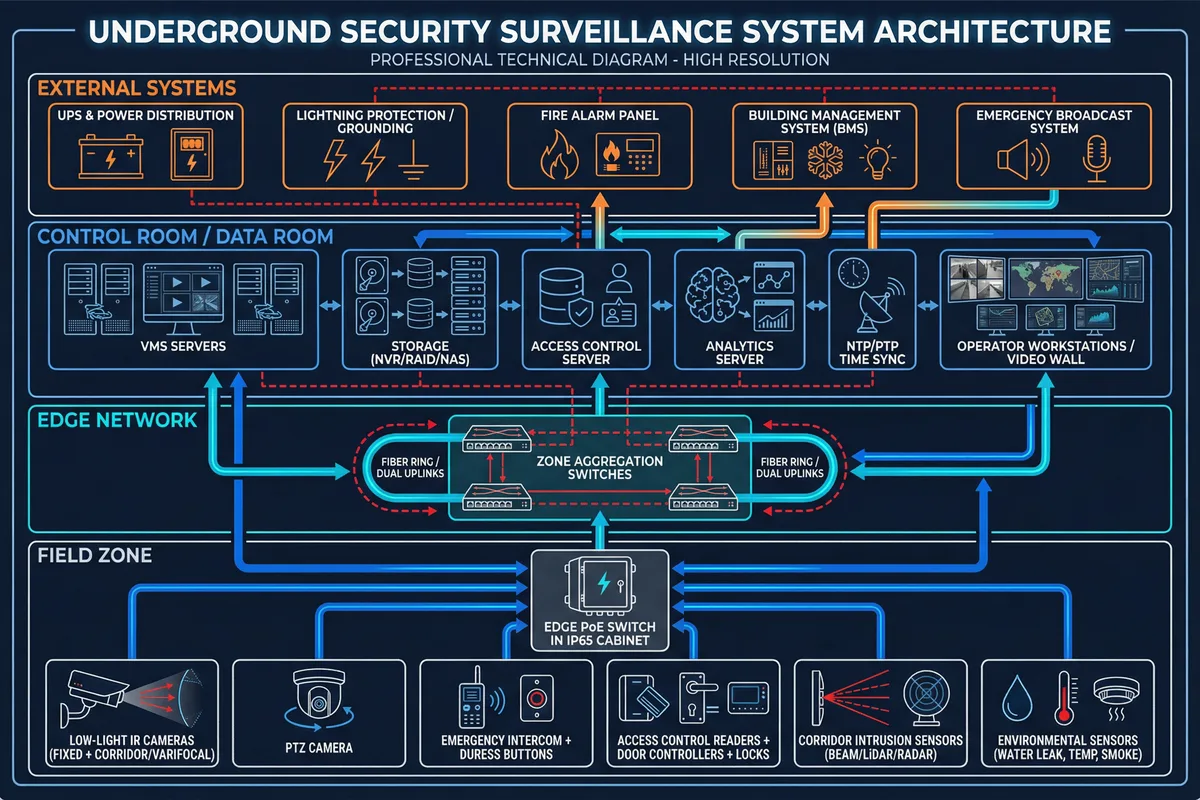
The field layer prioritizes IP rating, corrosion resistance, and mount accessibility. The edge network layer handles PoE delivery, VLAN segmentation, link redundancy, and surge/EMI mitigation. The platform layer manages recording, correlation, alarm workflow, and evidence handling. The integration layer connects fire/emergency systems, UPS alarms, door hardware interlocks, and reporting.
Main Functions
The system delivers seven core functional domains, each addressing a specific operational need in underground environments. The hub-and-spoke model below illustrates how all functions converge on the central Security & Emergency Operations capability, ensuring coordinated response across all subsystems.

| Function | Value | Key Implementation Points | Acceptance Focus |
|---|---|---|---|
| Low-light Usable Video | Identification & situational awareness in <20 lux | Large sensor, low-noise ISP, IR with controlled reflection, WDR, anti-fog, correct mounting angles | Target recognition at defined distance; glare control; IR hotspot check |
| Entrance & Access Control | Restricts rooms, manages visitor flow | OSDP readers, secure controller cabinet, fail-secure/fail-safe by egress policy | Door open time, forced-open alarms, offline operation, audit log completeness |
| Corridor/Line-crossing Protection | Detects intrusion in passages/tunnels | Line-crossing analytics + corridor sensors (beam/LiDAR/radar) for harsh dust/low-light | Detection rate, false alarm rate under dust/exhaust, alarm latency |
| Emergency Distress & Intercom | Rapid help request in enclosed zones | IP intercom, noise suppression, clear signage, integrated alarm workflow | Intelligibility (SNR), call setup time, camera pop-up linkage |
| Alarm Linkage & Response | Reduces operator reaction time | Event correlation rules, preset PTZ, nearby camera auto-display, output relays | End-to-end linkage time, correct camera association, audit trail |
| Link Reliability & Survivability | Function under partial failures | Redundant uplinks/rings, UPS for core, server failover, local SD fallback | Failover drills, packet loss/jitter thresholds, recording continuity |
| Sustainable O&M | Reduces downtime and cost | Remote health monitoring, modular spares, service loops, label standards | MTTR simulation, spare replacement steps validated |
Chapter Navigation
This guide is organized into twelve chapters, progressing from system fundamentals through design methodology, scenario selection, architecture, product interfaces, security, support systems, tools, calculators, quality acceptance, installation, and ongoing operations and maintenance.
Underground Environment Envelope
Underground and enclosed spaces present a unique combination of environmental stressors that directly influence system design decisions. The following table summarizes the baseline environmental parameters that this guide addresses, along with their design implications.
| Parameter | Typical Range | Design Implication |
|---|---|---|
| Ambient Temperature | 0 – 45 °C | Cabinet ventilation, dehumidification, PoE derating at high temps |
| Relative Humidity | 20 – 98% (condensation possible) | IP66/IP67 housings, breathable membranes, desiccants, heater strips |
| Illuminance | 5 – 80 lux (often <20 lux) | Starlight sensors, IR illumination, WDR ≥120 dB |
| EMI Exposure | Mild to strong (VFD/traction power) | Shielded cabling, fiber backbone in high-EMI zones, proper grounding |
| Dust / Particulates | Vehicle exhaust, logistics dust | Sealed housings, sensor fusion (radar + video), adaptive thresholds |
| Noise / Echo | High reverberation in corridors | Echo/noise suppression on intercoms, SNR-validated alarm audibility |
| Corrosion Exposure | Mild to moderate (coastal chlorides) | Marine-grade connectors, stainless fasteners, gel-filled glands |
| Availability Target | 99.9% for critical zones | Dual uplinks, UPS ≥30–60 min, server failover, SD fallback |