Support & Integration
7.1 Supporting Equipment Overview
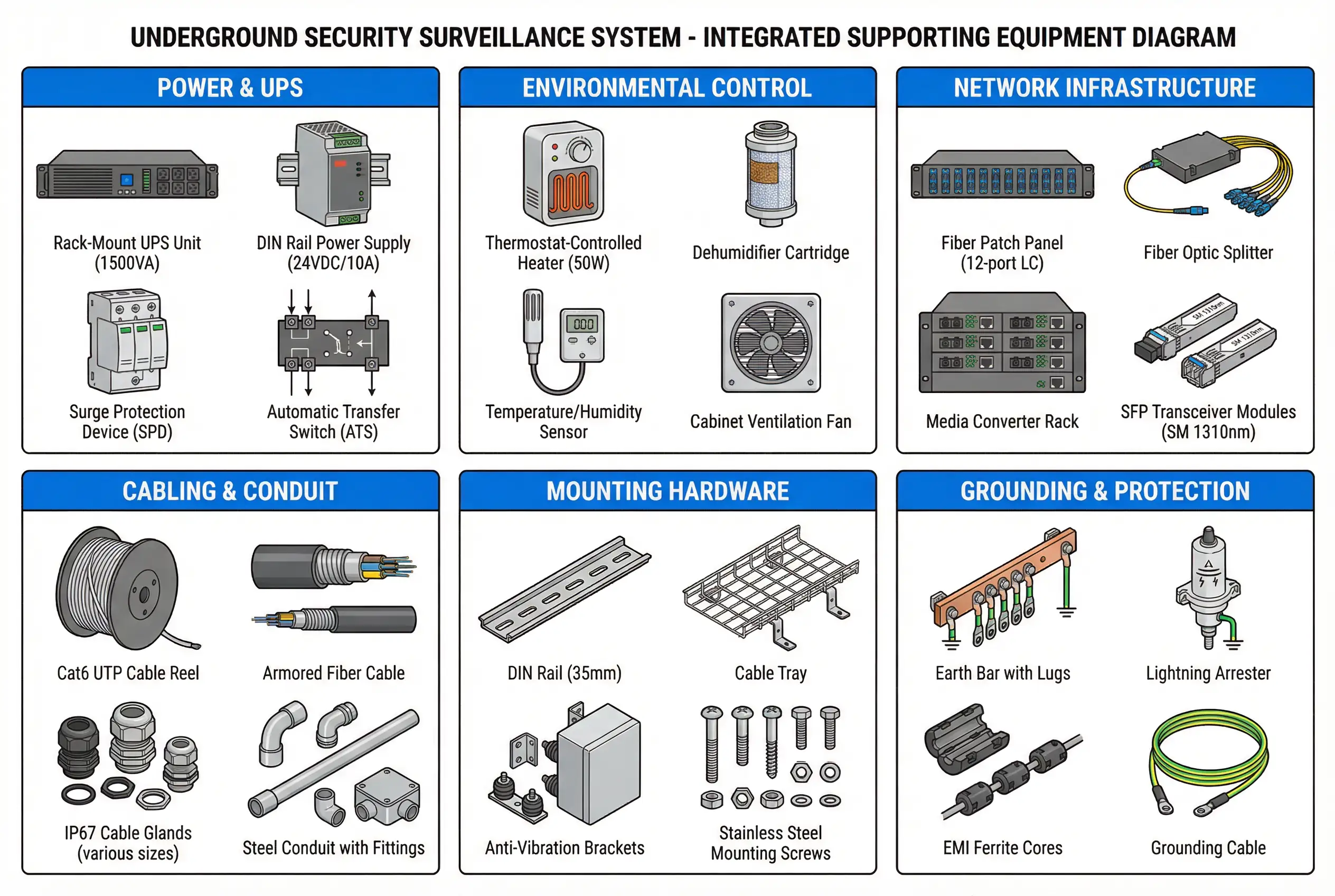
A complete underground security surveillance system requires a comprehensive set of supporting equipment beyond the core cameras, switches, and VMS. These supporting components — power infrastructure, environmental control, network accessories, cabling, mounting hardware, and grounding — are often overlooked during budgeting but are critical to long-term system reliability. The integrated diagram below shows all six categories of supporting equipment in a single reference view, enabling engineers to plan procurement and installation in a coordinated manner.
The six categories are: Power & UPS (ensuring continuous operation during mains outages), Environmental Control (protecting electronics from humidity and temperature extremes), Network Infrastructure (fiber management and media conversion), Cabling & Conduit (physical cable protection and routing), Mounting Hardware (secure and vibration-resistant device mounting), and Grounding & Protection (lightning and surge protection, EMI suppression). Each category has specific requirements for underground environments that differ from standard surface installations.
7.2 Power & UPS Requirements
Power continuity is the single most critical supporting requirement for underground surveillance systems. A power failure that disables cameras and access control simultaneously creates a security blind spot precisely when it may be most needed — during an emergency evacuation or a deliberate attack. The UPS sizing must account for the full PoE load of all connected devices, the field cabinet heater/dehumidifier load, and a minimum 2-hour backup duration for critical zones (4 hours recommended for high-security applications).
| Component | Specification | Selection Criteria | Underground-Specific Notes |
|---|---|---|---|
| Rack-mount UPS | 1000–3000 VA, online double-conversion | Size to 150% of actual load; online type only (no line-interactive for critical) | Verify operating temp range; battery life reduced at high temp — derate accordingly |
| DIN Rail Power Supply | 24 VDC, 5–20 A, DIN rail mount | Input voltage range 85–264 VAC; efficiency >90%; UL/CE certified | Redundant PSU recommended for critical zones; monitor output with NMS |
| Surge Protection Device (SPD) | Type 2 SPD, 20 kA per phase | IEC 61643-11 compliant; fit at cabinet entry point | Mandatory in areas with lightning risk or near high-voltage equipment |
| Automatic Transfer Switch (ATS) | 2-pole, 63 A, <20 ms transfer time | For dual-mains or mains+generator configurations | Required for high-availability installations; test transfer monthly |
7.3 Environmental Control
Underground environments are characterized by high relative humidity (often 80–95% RH), limited ventilation, and significant temperature cycling between day and night or between seasons. Without active environmental control inside field cabinets, condensation forms on PCBs and connectors, leading to corrosion, short circuits, and premature failure. The combination of a thermostat-controlled heater and a dehumidifier cartridge is the minimum requirement for all underground field cabinets. Temperature and humidity sensors with remote monitoring via SNMP or Modbus provide early warning of environmental excursions.
| Component | Specification | Set Point | Notes |
|---|---|---|---|
| Thermostat-Controlled Heater | 50–100 W, DIN rail mount, 24 VDC or 230 VAC | ON below +5°C, OFF above +15°C | Prevents condensation during cold startup; select wattage based on cabinet volume |
| Dehumidifier Cartridge | Silica gel or Peltier-type, 230 VAC | Target RH <60% inside cabinet | Silica gel type requires periodic regeneration; Peltier type is maintenance-free |
| Temp/Humidity Sensor | ±0.5°C, ±3% RH, RS-485 Modbus or 4–20 mA | Alert above 40°C or 80% RH | Connect to NMS for remote monitoring; log data for trend analysis |
| Cabinet Ventilation Fan | 24 VDC, IP54, thermostat-controlled | ON above 35°C, OFF below 30°C | Use only if cabinet has filtered air inlet; do not use in high-dust or high-humidity areas without filter |
7.4 Third-Party System Integration
Underground security surveillance systems rarely operate in isolation. They must integrate with building management systems (BMS), fire alarm systems (FAS), public address systems (PA), elevator control systems, and in some cases, SCADA systems for industrial facilities. The integration architecture must define the data flows, protocols, and event triggers between each system. The following table maps the key integration points and the recommended integration method for each.
| External System | Integration Type | Protocol / Interface | Trigger / Data Flow | Priority |
|---|---|---|---|---|
| Fire Alarm System (FAS) | Alarm-triggered recording + door release | Dry contact input to ACS; OPC-UA or BACnet to BMS | FAS alarm → ACS unlocks all fire exit doors → VMS starts pre-alarm recording on zone cameras | Mandatory |
| Building Management System (BMS) | Environmental data sharing + alarm relay | BACnet/IP or Modbus TCP | BMS flood sensor → VMS alarm popup; BMS HVAC fault → cabinet temp alert | Recommended |
| Public Address System (PA) | Intercom-triggered PA announcement | SIP trunk or dry contact relay | Intercom call → PA zone announcement; VMS alarm → automated PA message | Recommended |
| Elevator Control | Access control integration | Wiegand or RS-485 to elevator controller | Valid card read → elevator floor access granted; ACS sends floor permission to elevator controller | Optional |
| SCADA / DCS | Alarm and event correlation | OPC-UA or MQTT | SCADA process alarm → VMS camera popup on affected zone; VMS motion alarm → SCADA event log | Optional (industrial only) |
| HR / Identity Management | Cardholder database sync | LDAP / Active Directory | HR system adds/removes employee → ACS automatically updates access rights; no manual ACS entry | Recommended |
Integration Design Rule: All third-party integrations must be documented in an Integration Design Document (IDD) before installation begins. The IDD must specify the protocol, data format, trigger conditions, failure behavior (fail-safe vs. fail-secure), and the responsible party for each integration point. Undocumented integrations are the leading cause of commissioning delays and post-handover defects.