Design Methods
2.1 Executable Principles & Basis
Effective underground security surveillance design is governed by a set of executable engineering principles — not abstract guidelines, but actionable rules with a defined basis, implementation approach, and verification method. These principles were derived from failure history, code requirements, and operational experience in underground environments. Each principle addresses a specific failure mode or constraint unique to underground and enclosed spaces.
The twelve principles below form the backbone of every design decision in this guide. They should be treated as mandatory constraints during the design phase, not optional best practices. When a site-specific condition conflicts with a principle, the conflict must be documented and resolved with engineering justification — not silently ignored.
1. Emergency-First Linkage
Distress and fire events must trigger camera pop-up + recording bookmark + operator workflow. Basis: safety operations and emergency response time requirements.
2. Image Usability Over Spec-Sheet
Validate DORI at site lux and wet-floor reflections, not just datasheet values. Basis: acceptance testing with real-world conditions including headlights and IR bounce.
3. EMI-Aware Topology
Fiber trunk mandatory in traction power and VFD zones; avoid copper parallel to power cables. Basis: EMC engineering and field failure analysis in metro environments.
4. Condensation Control
Choose IP66/IK10 enclosures, breathable membranes, and anti-fog measures. Basis: environmental reliability in high-RH underground spaces with thermal cycling.
5. Maintainability by Design
Front-access cabinets, service loops, quick-swap mounts, and consistent labeling. Basis: O&M cost reduction and MTTR targets in constrained-access environments.
6. Fail-Safe vs. Fail-Secure by Egress
Doors on escape routes must comply with egress codes; security must never block evacuation. Basis: fire code, life safety regulations, and liability management.
7. Redundancy Where It Matters
Dual uplinks + UPS for control room; SD fallback for critical cameras. Basis: 99.9% availability target for critical zones with graceful degradation for non-critical.
8. Least Privilege & Segmentation
Separate CCTV/ACS/IoT VLANs; role-based access control. Basis: cyber hygiene, network isolation to prevent lateral movement in case of compromise.
9. Deterministic Time
NTP/PTP with monitoring; consistent timestamps across all devices for evidence integrity. Basis: forensics requirements and legal admissibility of recorded evidence.
10. Lifecycle Cost (LCC)
Prioritize corrosion resistance and modular spares to reduce MTTR/MTBF penalties. Basis: total cost of ownership analysis showing maintenance dominates over 5-year horizon.
11. Dust/Exhaust Tolerance
Avoid over-reliance on pure video analytics in high-particulate corridors; combine with radar/LiDAR. Basis: failure history showing analytics false alarm rates exceeding 20/day in dusty tunnels.
12. Document Everything
Port maps, camera IDs, door logic, firmware baseline — all must be current and accessible. Basis: sustainable operations and incident investigation capability.
2.2 Failure Cause → Recommendation
Underground environments produce a distinctive set of failure patterns that differ significantly from above-ground installations. The table below maps each typical failure to its underlying mechanism, the recommended engineering countermeasure, and the verification method that confirms the countermeasure is effective. This mapping should be used during design review to ensure each failure mode has been explicitly addressed.
| Typical Failure | Mechanism in Underground Spaces | Recommendation | Verification |
|---|---|---|---|
| Night glare / IR bloom | Wet floors reflect IR at high angles, saturating sensor | Use IR angle control, lower IR power, polarizing lens if appropriate; mount camera at ≥45° to floor | Night test with wet floor simulation; check for hotspots in live view |
| Lens fogging | Condensation on cold lens surface + poor housing seal | IP66 housing, desiccant pack, heater strip, breathable membrane; verify gasket integrity | RH logging + visual inspection after thermal cycle; spray test on cabinet |
| Corrosion at connectors | High RH + chloride salts (coastal sites) attacking terminals | Marine-grade connectors, gel-filled glands, stainless fasteners, anti-corrosion spray on terminals | Salt fog class evidence from supplier; annual visual inspection |
| False intrusion alarms | Dust/exhaust particles, airflow, and shadows trigger video analytics | Multi-sensor fusion (radar + video), adaptive thresholds, exclude high-particulate periods | 7-day false alarm log during normal operations; target <2/day/zone |
| Random camera reboot | PoE overload at elevated cabinet temperature (derating) | PoE budget margin 30% above peak load; cabinet ventilation; monitor PoE telemetry | PoE telemetry review under peak temperature; load test at 45 °C |
| Network storms | Misconfigured loops, missing RSTP/ERPS, unmanaged switches | ERPS/RSTP on all managed switches; storm control; VLAN hygiene; no unmanaged switches | Loop test in staging environment; verify ERPS convergence time <50 ms |
| Evidence timestamp dispute | NTP time drift on isolated devices, no monitoring | NTP with monitoring and alerting; PTP for critical cameras; maximum drift <1 s/month | Time drift measurement report; monthly automated check |
| Door lock unsafe in fire | Wrong fail mode selected; fire input not wired or tested | Code-driven lock selection per egress policy; fire input overrides tested in integrated drill | Fire linkage test with actual fire panel signal; door releases within 3 s |
2.3 Core Decision Logic
The design decision process begins with a thorough scene type assessment, followed by evaluation of four key environmental parameters: illuminance (lux), humidity and ingress risk, EMI level, and maintenance access constraints. These parameters drive the selection of camera class, cabinet IP rating, trunk type, redundancy level, and sensor fusion strategy. The output is one of three solution packages — Standard, Hardened, or High Availability — each with a defined BOM profile and acceptance criteria.
The decision tree diagram below provides a visual guide to this process. Each branch represents a decision point with clear criteria, and the final nodes specify the recommended solution package along with its key BOM traits. This tree should be completed during the design phase and included in the design package as evidence of the selection rationale.
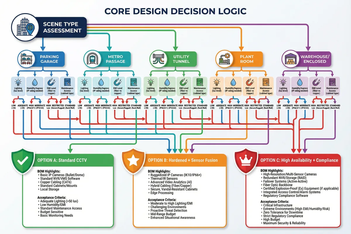
Decision Rule: If any single parameter (lux, RH, EMI, or maintenance access) falls into the "severe" category, the solution package must be upgraded to at least Option B (Hardened + Sensor Fusion). Two or more severe parameters mandate Option C (High Availability + Compliance).
2.4 Key Design Dimensions
Every underground surveillance system design must be evaluated across seven key dimensions. These dimensions provide a structured framework for trade-off analysis, ensuring that no critical aspect is overlooked in favor of cost reduction or schedule pressure. Each dimension has measurable indicators that can be tracked through the design, installation, and acceptance phases.
Performance & Experience
DORI at target distance, alarm latency ≤2 s, intercom intelligibility (MOS ≥3.5)
Stability & Reliability
Redundancy paths, MTBF targets, storage integrity (RAID6 or better), 99.9% uptime
Maintainability & Replaceability
Modularity, labeling standards, access clearances, MTTR <4 h for critical zones
Compatibility & Expansion
ONVIF Profile S/G/T, open API, spare ports and rack U-space for 20% growth
LCC / TCO
Energy consumption, spare parts inventory cost, downtime cost per hour
Energy & Environment
PoE efficiency, cabinet heat dissipation, dehumidification power budget
Compliance & Certification
IP/IK ratings, EMC, fire/egress code, privacy signage, retention policy compliance
| Dimension | Key Metrics | Typical Underground Target | Design Lever |
|---|---|---|---|
| Performance | DORI, alarm latency, MOS | DORI per design distance; latency ≤2 s; MOS ≥3.5 | Lens selection, sensor size, QoS, echo cancellation |
| Stability | Uptime, MTBF, storage integrity | 99.9% critical zones; RAID6; no single point of failure | Redundant uplinks, UPS, server failover, SD fallback |
| Maintainability | MTTR, access time, spare availability | MTTR ≤4 h P2; ≤1 h P1; spares on-site | Front-access cabinets, quick-swap mounts, labeled ports |
| Compatibility | ONVIF compliance, API version | ONVIF Profile S/G; VMS API v2+; OSDP v2 | Multi-vendor spec, API testing in staging |
| LCC/TCO | 5-year total cost | Maintenance <15% of capex/year | Corrosion resistance, modular spares, remote diagnostics |
| Energy | Total PoE load, cabinet heat | PoE load <70% derated budget; cabinet ≤40 °C | PoE scheduling, ventilation, dehumidification |
| Compliance | IP/IK, EMC, fire code | IP66 minimum; IK10 for vandal zones; EMC Class B | Product certification, fire drill, privacy audit |