Architecture Design
4.1 Typical System Topology
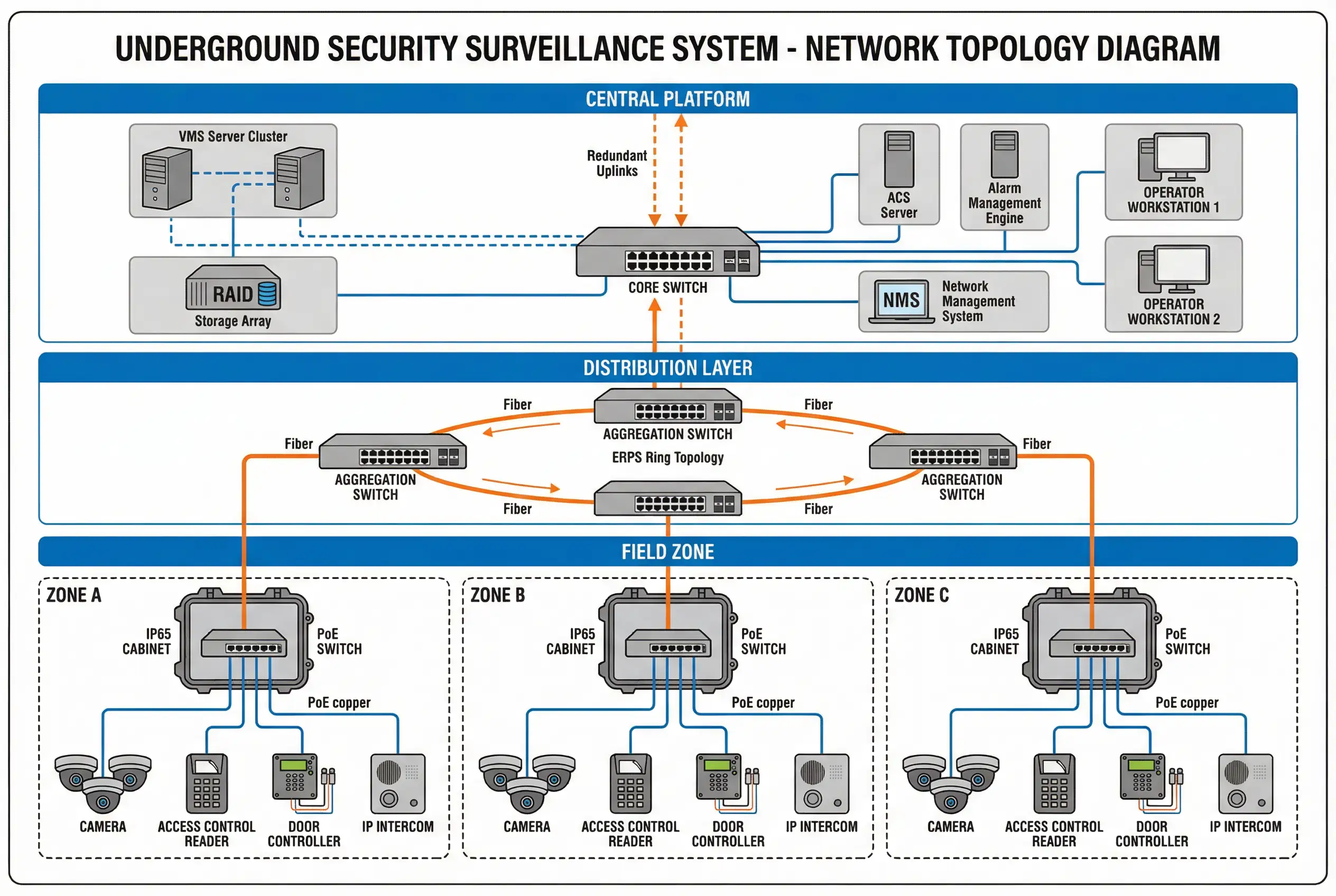
The reference topology for underground security surveillance systems follows a three-tier hierarchical architecture: Central Platform, Distribution Layer, and Field Zone. This structure mirrors the physical organization of underground facilities — a central control room at the surface or in a protected basement, intermediate distribution points at zone boundaries, and field cabinets distributed throughout each monitored zone. The topology is designed to minimize copper cable runs (which are susceptible to EMI and corrosion), maximize fiber utilization for inter-tier links, and provide independent zone operation in the event of uplink failure.
The distribution layer uses ERPS (Ethernet Ring Protection Switching) to provide sub-50 ms failover when a fiber segment is cut or a switch fails. Each field zone cabinet connects to the ring via two independent fiber paths, ensuring that no single fiber break can isolate a zone. Critical cameras in each zone are configured with onboard SD card recording as a fallback, ensuring evidence continuity even during network outages.
Central Platform
VMS cluster, storage array, ACS server, alarm engine, operator workstations, NMS. Redundant uplinks to distribution layer. Located in protected, climate-controlled room.
Distribution Layer
Aggregation switches in ERPS ring topology. Fiber connections to central platform and all field zone cabinets. Provides sub-50 ms failover on any single fiber break.
Field Zone
IP65 cabinet with industrial PoE switch, fiber media converter, SPD, and UPS. Connects to cameras, readers, controllers, intercoms, and sensors within the zone.
| Tier | Key Equipment | Connection Type | Redundancy | Failure Impact |
|---|---|---|---|---|
| Central Platform | VMS cluster, storage, ACS, alarm engine | 10GbE to core switch | Active-active cluster, RAID6 storage | Failover to secondary VMS node; no recording loss |
| Distribution (Ring) | Aggregation switches (2–4 per ring) | Single-mode fiber, 1–10 GbE | ERPS ring, <50 ms failover | Single fiber break: ring heals; dual break: zone isolated |
| Field Zone Cabinet | Industrial PoE switch, media converter, SPD | Fiber uplink + PoE copper | SD fallback on critical cameras | Cabinet failure: zone offline; SD preserves evidence |
| Field Devices | Cameras, readers, controllers, intercoms | PoE Cat6, RS-485, dry contact | Onboard SD (cameras), offline rules (ACS) | Individual device failure; no zone-wide impact |
4.2 Device Wiring & Connection Diagram
The field cabinet wiring diagram defines the physical connection standard for all underground zone cabinets. It specifies cable types, conductor gauges, maximum run lengths, connector types, and grounding requirements for each device category. Adherence to this standard is mandatory for all installations and must be verified during the acceptance inspection. Deviations require written engineering justification and approval before installation.
The diagram shows a single IP65 field cabinet with its internal DIN rail layout and all external device connections. Key wiring rules include: fiber uplink uses single-mode LC connectors with factory-terminated pigtails; PoE camera cables use Cat6 UTP with RJ45 connectors and maximum 90 m horizontal run (plus 10 m patch); RS-485 bus for access control readers uses 2-wire shielded cable with shield grounded at one end only (cabinet end); door lock power uses 18 AWG 2-core with maximum 50 m run at 12 VDC; and all cable entries use IP67 cable glands with appropriate strain relief.

| Connection | Cable Type | Conductor | Max Run | Connector | Notes |
|---|---|---|---|---|---|
| Fiber Uplink | SMF OS2 9/125 µm | — | 10 km (standard) | LC/APC | Factory-terminated pigtails; no field splices in cabinet |
| PoE Camera | Cat6 UTP | 23 AWG | 90 m horizontal | RJ45 T568B | Avoid parallel runs with power cables; steel conduit in EMI zones |
| RS-485 (ACS readers) | 2-wire shielded | 24 AWG | 1200 m (OSDP) | Terminal block | Shield grounded at cabinet end only; 120 Ω termination at far end |
| Door Lock Power | 2-core stranded | 18 AWG | 50 m at 12 VDC | Terminal block | Voltage drop <0.5 V at full load; fused at cabinet |
| Dry Contact (sensor/button) | 2-core stranded | 22 AWG | 100 m | Terminal block | Use shielded cable in high-EMI areas |
| IP Intercom | Cat6 UTP | 23 AWG | 90 m | RJ45 T568B | Same rules as PoE camera; verify PoE class compatibility |
| Grounding | Green/yellow stranded | 6 AWG | <5 m to earth bar | Lug + earth bar | Resistance <1 Ω; verify with earth tester at acceptance |
Wiring Safety Rule: Never run PoE camera cables in the same conduit as 230 VAC power cables. Maintain a minimum 300 mm separation between low-voltage signal cables and high-voltage power cables. In areas with VFD (variable frequency drive) equipment, use shielded Cat6 or fiber for all camera connections within 5 m of the VFD.
4.3 Network Design Parameters
Network design for underground surveillance systems must account for the high bandwidth demands of multi-megapixel video streams, the latency sensitivity of access control and alarm events, and the reliability requirements of a 24/7 critical infrastructure system. The following parameters define the minimum acceptable network design for each solution package.
| Parameter | Package A (Standard) | Package B (Hardened) | Package C (High Availability) |
|---|---|---|---|
| Uplink Bandwidth | 1 GbE per zone | 1 GbE per zone + 10% headroom | Dual 1 GbE or 10 GbE per zone |
| Ring Topology | Optional | Mandatory (ERPS) | Mandatory (ERPS + dual ring) |
| Failover Time | <30 s (STP) | <50 ms (ERPS) | <50 ms (ERPS) + VMS HA |
| VLAN Segmentation | CCTV + ACS VLANs | CCTV + ACS + IoT VLANs | CCTV + ACS + IoT + Mgmt VLANs |
| QoS | Video priority (DSCP AF41) | Video + ACS priority | Full QoS policy with policing |
| NTP Accuracy | ±1 s | ±100 ms (NTP with monitoring) | ±1 ms (PTP for critical cameras) |
| Bandwidth Utilization Target | <80% peak | <70% peak | <60% peak (30% headroom) |
Bandwidth Calculation Reminder: Use the calculator in Chapter 9 to compute the total video bandwidth for your camera count and resolution mix. Add 20% overhead for control traffic, SNMP, and NTP. The result should not exceed the target utilization percentage for the selected solution package.