Installation & Debugging
11.1 Installation Requirements
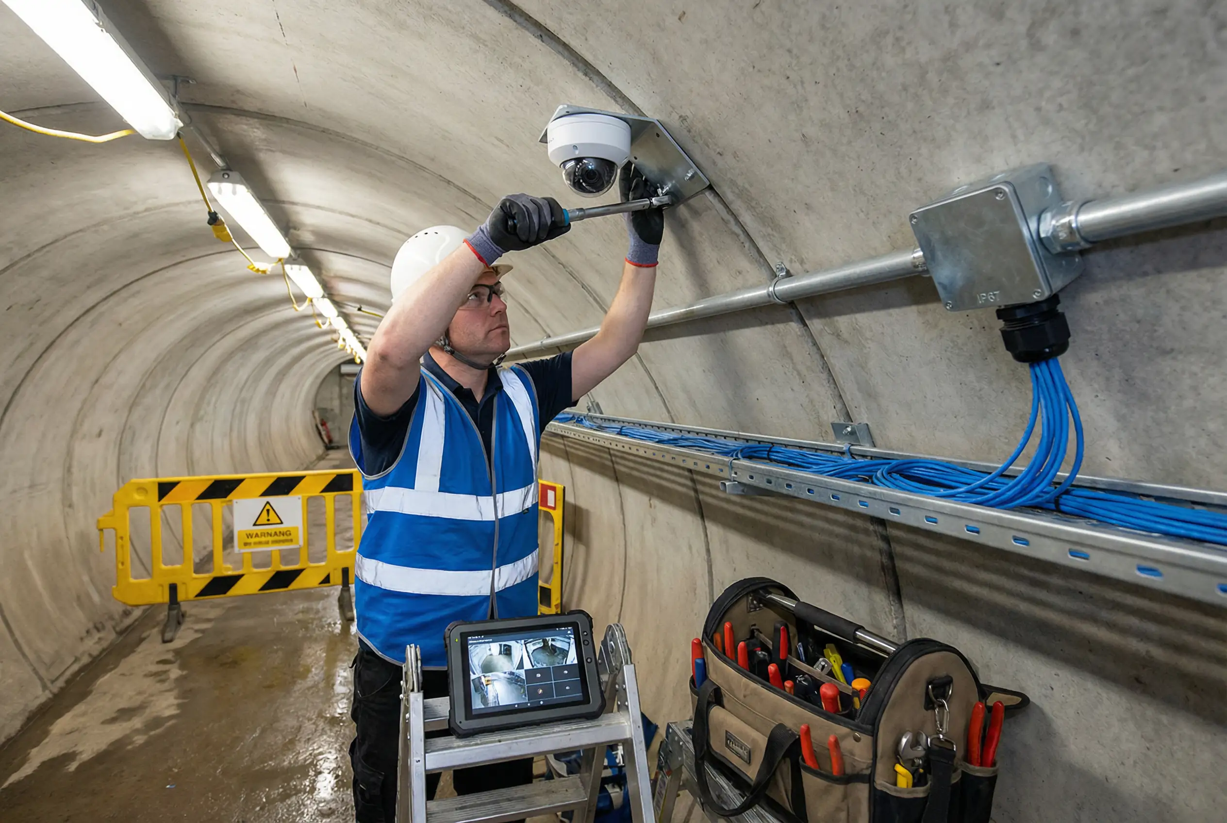
Underground security surveillance installations must comply with a set of requirements that go beyond standard surface installations. The confined space, high humidity, limited ventilation, and potential for explosive atmospheres create a working environment that demands rigorous safety planning, specialized tools, and experienced personnel. The photograph below shows a professional installation in progress in an underground tunnel, illustrating the key requirements: safety equipment, proper cable management, IP67-rated junction box, conduit routing, and real-time commissioning verification using a tablet.
The installation sequence must follow a strict top-down, inside-out order: infrastructure (conduit, cable trays, junction boxes) first, then cabling, then devices, then commissioning. This sequence minimizes rework and ensures that each layer of the installation can be inspected and tested before the next layer is added. Deviating from this sequence — for example, mounting cameras before running cables — leads to poor cable management and is a common cause of acceptance failures.
11.2 Pre-Installation Checklist
Before any installation work begins underground, a pre-installation checklist must be completed and signed off by the site supervisor. This checklist covers safety, material readiness, and site conditions. Proceeding without completing this checklist is a safety violation and may result in work stoppage.
Confined Space Entry Permit
Obtain a valid confined space entry permit. Verify gas levels (O2, LEL, CO, H2S) with a 4-gas detector. Ensure rescue equipment is on standby at the entry point.
Electrical Isolation (LOTO)
Lock out and tag out all electrical circuits in the work area. Verify isolation with a voltage tester. Obtain a permit to work (PTW) for electrical work if required by site rules.
Material and Equipment Check
Verify all materials are on-site and match the approved material submittal. Check that all tools are calibrated and in good condition. Confirm IP-rated cable glands match cable diameters.
Design Drawing Review
Review the latest revision of installation drawings. Confirm camera positions, cable routes, and junction box locations match the approved design. Note any site conditions that differ from the drawings.
Confined Space Safety: Never enter an underground space without a valid confined space entry permit and a gas test result less than 30 minutes old. Assign a dedicated standby person at the entry point who maintains continuous communication with workers inside. In the event of any gas alarm, evacuate immediately and do not re-enter until the space has been re-tested and cleared by a competent person.
11.3 Step-by-Step Installation Procedure
The following table provides the detailed step-by-step installation procedure for a standard underground zone. Each step includes the responsible party, the tools required, the acceptance criterion, and the documentation required. Steps must be completed in the order listed; do not proceed to the next step until the current step has been verified and signed off.
| Step | Activity | Responsible | Tools | Acceptance Criterion |
|---|---|---|---|---|
| 1 | Install cable trays and conduit supports | Mechanical contractor | Drill, anchors, level | Supports level and plumb; spacing ≤1.5m; load rating confirmed |
| 2 | Install junction boxes and field cabinets | Electrical contractor | Drill, level, torque driver | Boxes level; IP65 minimum; cable entry knockouts sealed; earthing lug installed |
| 3 | Pull fiber optic backbone cable | Low-voltage contractor | Cable puller, fish tape, OTDR | OTDR test report: insertion loss <0.5 dB/km; no reflections; both ends labeled |
| 4 | Pull Cat6 camera drop cables | Low-voltage contractor | Cable puller, cable tester | TIA-568 wiremap pass; length <90m; both ends labeled; no sharp bends |
| 5 | Terminate fiber in ODF / patch panels | Fiber specialist | Fusion splicer, cleaver, OTDR | Splice loss <0.1 dB; connector insertion loss <0.3 dB; end-face inspection passed |
| 6 | Install PoE switches and power supplies in cabinets | Low-voltage contractor | Torque driver, DIN rail cutter | Switch secured on DIN rail; power supply earthed; cabinet heater/dehumidifier installed |
| 7 | Mount camera brackets | Low-voltage contractor | Drill, torque driver, level | Bracket torqued to specification; anti-vibration mount installed where required; earthing bonded |
| 8 | Install cameras and connect cables | Low-voltage contractor | Torque driver, IP67 gland tool | Camera secured; IP67 gland torqued; cable strain relief installed; dome cover clean |
| 9 | Power up and IP address assignment | Network engineer | Laptop, network scanner | All cameras reachable by ping; IP addresses match design; no duplicate IPs |
| 10 | Add cameras to VMS and configure | VMS engineer | VMS client, laptop | All cameras added; recording schedules configured; motion detection zones set |
| 11 | Adjust camera angles and focus | Low-voltage contractor + VMS engineer | Laptop with live view, angle meter | Coverage area matches design; focus sharp at target distance; IR illumination uniform |
| 12 | Final testing and acceptance | Project manager + client | All test tools | All items in acceptance checklist (Chapter 10) passed |
11.4 Debugging Common Issues
Underground installations frequently encounter a set of recurring commissioning issues that differ from surface installations. The following table lists the most common issues, their root causes, and the recommended debugging steps. Systematic debugging using the steps below will resolve the majority of commissioning issues within the first day of testing.
| Symptom | Most Likely Root Cause | Debugging Steps |
|---|---|---|
| Camera not reachable by ping | PoE not delivering power; IP address conflict; cable fault | 1. Check PoE switch port status LED. 2. Test cable with cable tester. 3. Check IP address assignment. 4. Try different switch port. |
| Blurry or out-of-focus image | Varifocal lens not adjusted; dome cover scratched; condensation inside dome | 1. Access camera web UI and use auto-focus. 2. Inspect dome cover. 3. If condensation, check IP seal and add desiccant. |
| IR illumination uneven / hotspot | Camera too close to wall; IR power too high; dirty dome | 1. Reposition camera away from wall. 2. Reduce IR intensity in camera settings. 3. Clean dome cover. |
| Video stream stuttering or dropping | Network congestion; PoE budget exceeded; cable fault | 1. Check switch CPU and bandwidth utilization. 2. Verify PoE budget calculation. 3. Run cable test on affected run. |
| Recording gaps in VMS | Storage full; NVR/VMS service crashed; camera offline during gap | 1. Check storage utilization in VMS. 2. Check VMS service logs. 3. Cross-reference camera online history with recording gaps. |
| False motion alarms | Camera vibration; IR reflection from water; sensitivity too high | 1. Check camera mount for vibration. 2. Exclude reflective areas from motion zone. 3. Reduce motion sensitivity in VMS. |
Commissioning Tip: Always commission cameras from the control room outward — start with the NVR/VMS server, then the core switches, then the field switches, and finally the cameras. This ensures that each layer of the system is verified before the next layer is added, making it much easier to isolate the cause of any issue.