System Components
1.1 System Architecture
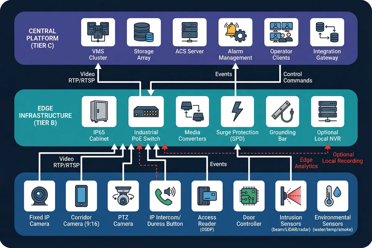
The underground security surveillance system is organized into three functional tiers, each with clearly defined responsibilities and interfaces. This three-tier decomposition ensures that field devices, edge infrastructure, and central platform components can be independently specified, installed, and maintained — a critical requirement given the constrained access conditions typical of underground environments.
Tier A (Field Devices) encompasses all sensing and actuation endpoints: cameras, intercoms, readers, controllers, locks, and environmental sensors. Tier B (Edge Infrastructure) provides the first-hop power and network services within each zone, including IP65-rated cabinets, industrial PoE switches, media converters, surge protection, and optional local NVR for edge recording. Tier C (Central Platform) hosts the VMS cluster, storage array, access control server, alarm management engine, operator workstations, and integration gateways.
Data flows are clearly directional: video streams travel upward via RTP/RTSP from cameras to the VMS; events from ACS controllers and sensors flow to the alarm engine via ONVIF events or proprietary APIs; control commands travel downward for PTZ positioning, door unlock, and relay triggers. Red dashed paths in the architecture diagram indicate optional components such as local edge recording appliances or edge analytics modules that may be deployed in zones with unreliable uplinks.
Core, Optional, and Supporting Components
Core (Mandatory)
- IP cameras (fixed + corridor) + PoE switching
- VMS/recording platform + operator client
- Access control at all entrances
- Alarm workflow engine
- Fiber backbone between zones
Optional (Scenario-Driven)
- PTZ cameras for large open areas
- Edge analytics appliances
- Local NVR in remote/isolated zones
- Audio analytics for distress detection
- Radar/LiDAR sensors for harsh corridors
Supporting (Infrastructure)
- UPS and power distribution
- Grounding and surge protection
- IP65+ cabinets with dehumidification
- Fire and emergency linkage interfaces
- Structured cabling and conduits
Deployment Boundary Rule: Field cabinets are placed per zone to minimize copper cable length and support independent maintenance. Central equipment must reside in a dry, temperature-controlled room. If a dedicated room is not feasible, use sealed racks with active dehumidification and temperature monitoring.
1.2 Components & Functions
Each component in the system has a defined responsibility, a set of inputs and outputs, measurable key performance indicators (KPIs), and known mismatch risks that arise from incorrect specification or installation. Understanding these relationships is essential for producing a BOM that is fit for purpose rather than merely compliant on paper.
The component inventory diagram below presents each device as an icon with labeled input and output flows, providing a visual reference for the I/O relationships described in the table. Particular attention should be paid to the mismatch risk column, as many underground system failures originate from specification errors rather than product defects — for example, using the wrong IR power level on a wet floor, or selecting a fail-safe lock on an emergency egress door without verifying the egress code requirement.

| Component | Responsibility | Inputs | Outputs | Key KPIs | Common Mismatch Risk |
|---|---|---|---|---|---|
| Low-light IP Camera | Capture usable video in <20 lux | PoE, time sync | H.264/H.265 stream, events | Min illumination 0.005–0.05 lux (color), WDR ≥120 dB | IR reflection causing overexposure; lens fogging |
| Corridor Camera (9:16) | Long passage coverage | PoE | Corridor stream | DORI at defined distance, corridor mode | Wrong aspect ratio → blind areas at passage ends |
| IR Illuminator (external) | Improve low-light imaging | 12/24 VDC | IR light output | Range 15–80 m, beam angle | Hotspots, glare on wet floor causing overexposure |
| PTZ Camera | Wide-area tracking and patrol | PoE++/Hi-PoE | PTZ stream, preset positions | Preset time <2 s, tracking stability | Mount vibration; insufficient PoE budget for Hi-PoE |
| VMS Server | Recording, alarm, evidence | Network, storage | Live view, playback, alarms | Concurrent streams, storage IOPS, failover time | Undersized storage; no failover configured |
| PoE Access Switch | Power + L2/L3 networking | AC/UPS | PoE ports, uplink | PoE budget (W), MTBF, port count | Power derating in hot cabinets causing random reboots |
| Fiber Uplink | Long-distance + EMI immunity | Switch SFP | Trunk link | Loss budget, redundancy path | Wrong fiber type or connector contamination |
| Access Reader (OSDP) | Credential capture | Controller bus | Auth data | Secure channel, tamper detection | Wiegand used instead → no encryption |
| Door Controller | Door logic and events | Readers, sensors | Lock control, events | Offline rules, log capacity | Controller placed in accessible spot → sabotage risk |
| Locks (maglock/strike) | Physical door control | Relay power | Door secured/open | Holding force, fail mode | Fail-safe vs. fail-secure wrong selection vs. egress code |
| Duress Button | Emergency trigger | User press | Alarm event | Latency <1 s | Poor placement, no signage, no regular test |
| IP Intercom | Two-way communication | PoE | Voice + event | MOS/SNR, echo cancellation | Echo/reverb in tunnels → unintelligible audio |
| Corridor Sensor (beam/LiDAR/radar) | Intrusion detection | Power | Alarm relay/IP | Detection rate, false alarm rate | Dust/exhaust causing false alarms without fusion |
| Water Leak Sensor | Seepage detection | Probe | Alarm | Response time <30 s | Poor routing, corrosion of probe contacts |
1.3 Working Principles
Understanding the system's operational lifecycle — from startup through normal operation, abnormal degradation, and recovery — is essential for both commissioning engineers and O&M teams. The system is designed to fail predictably and recover gracefully, with each degradation mode having a defined detection mechanism, response procedure, and recovery path.
Operational Lifecycle
| Phase | Key Steps | Success Criteria |
|---|---|---|
| Startup | Power-on → switches boot → time sync (NTP/PTP) → cameras register to VMS (ONVIF/RTSP) → ACS controllers sync users/policies → alarm rules load → health checks pass → system "armed" by schedule or operator | All devices registered, time sync <1 s, health dashboard green |
| Normal Operation | Cameras stream continuously; events (door open, line-crossing, duress) enter alarm engine; workflow triggers video pop-up, bookmarks, operator acknowledgment, and optional outputs (sirens/PA/door lockdown) | Recording continuity, alarm latency <2 s, no false positives |
| Abnormal | System detects link/power/storage failures and degrades predictably; critical cameras fall back to SD; operator notified; non-critical functions suspended | Graceful degradation, no silent failures, all events logged |
| Recovery | Restore power/link → devices re-register → backlog sync (edge SD) → generate incident report → verify recording continuity | Evidence chain intact, all gaps documented, system re-armed |
Three Abnormal Chain Examples
The following examples illustrate how environmental and infrastructure failures cascade through the system, and how each chain is detected, contained, and resolved. These chains should be rehearsed during acceptance testing.
Chain 1: Cabinet Humidity → Lens Fog → Unusable Video
Image haze metric alarms on VMS + RH sensor alarm from cabinet environmental monitor exceeds threshold (e.g., RH >85%).
Switch camera to IR-only profile; increase shutter constraints to reduce haze impact; dispatch maintenance team; activate cabinet heater/dehumidifier remotely.
Clean lens with appropriate solvent; replace housing gasket; verify RH stable below threshold for 24 h; restore normal recording profile; document incident.
Chain 2: Uplink Fiber Break → Zone Isolated
Link-down event on aggregation switch + heartbeat loss from all devices in affected zone; VMS marks zone cameras as offline.
Ring protection (ERPS) reroutes traffic if ring intact; if total isolation, critical cameras record to onboard SD/local NVR; operator notified via alarm; patrol dispatched.
Repair or replace fiber segment; verify ring integrity; reconcile SD recordings to central storage; audit recording continuity; update as-built drawings.
Chain 3: PoE Budget Exceeded → Random Camera Reboots
PoE overload logs on switch SNMP; cameras flapping (repeated register/deregister cycles); recording gaps in VMS.
Enforce PoE class limits per port; redistribute high-power devices (PTZ, heaters) across switches; upgrade to PoE++ switch or add midspan injector for PTZ.
Run PoE budget test under peak temperature (derating factor applied); document port allocations in as-built records; set monitoring alert at 70% of derated budget.
Engineering Note: All three abnormal chains above are preventable through proper design — correct PoE budgeting with 30% margin, IP66 cabinet sealing with RH monitoring, and fiber ring topology with ERPS. The chains are documented here to support acceptance testing and O&M training, not as expected operational events.